
Starlink Mini & Gen 1-3 Waterproof Rocker Switch - 20A

Check the selected Tesla model, model year, and option before checkout. If this product has a Car Model or Compatible Model selector, choose the option that matches your vehicle.
- Use the product images and variant name to confirm the correct version.
- If you are unsure about fitment, contact Tesstudio with your Tesla model and production year before ordering.
Tesstudio installation support is available for Tesla owners who need help choosing, installing, or troubleshooting accessories.
Most Tesstudio accessories are designed for straightforward DIY installation. For powered upgrades, wiring, lighting, or large exterior parts, professional installation may be recommended.
Local installation and technical support
- Address: 14761 Franklin Ave # G, Tustin, CA 92780
- Technical support: +1 (657) 543-9876 or +1 (657) 565-1007
- Support hours: Monday-Friday, 8:30 AM-5:30 PM
The phone numbers above are for technical installation support only. For orders, shipping, returns, or general customer service, contact:
- Email: support@tesstudio.com
- WhatsApp: +1 714 317 9647
Tesstudio checks fit, material, and daily-use durability before listing products for Tesla owners.
- Eligible products include warranty support for non-human damage issues.
- If a product arrives damaged or does not fit as expected, keep the packaging and contact us with photos so we can help quickly.
In-stock items are usually processed within 1-2 business days. Delivery time depends on destination, product size, and stock status.
- Orders over $99 qualify for free standard shipping where available.
- Oversized, remote-area, pre-order, and special-market items follow the terms shown on the product page.
- Tracking is provided after dispatch.
Need help before or after purchase?
Contact Tesstudio support:
WhatsApp
+1 714 317 9647
Optionen auswählen
Turn Your Starlink DC Power Circuit On and Off Without Pulling the Plug
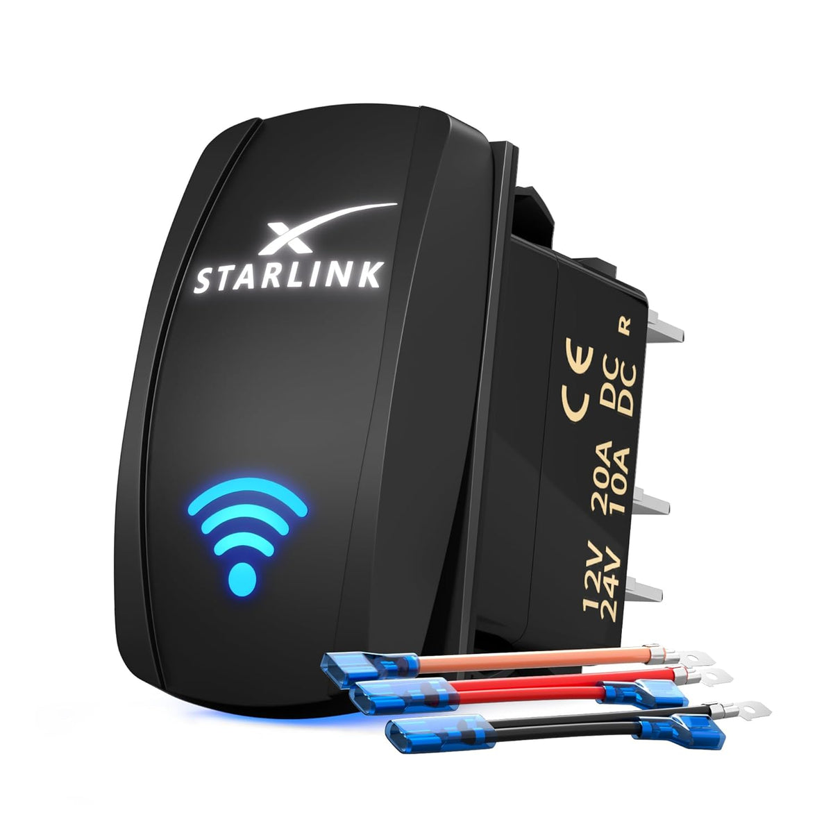
A compact 5-pin illuminated rocker switch for compatible Starlink Mini and Gen 1–3 DC power installations. Add a dedicated control point to an RV, van, truck, camper, marine or off-grid power panel.

Stop Disconnecting the Power Cable Every Time You Want Starlink Off
Power Control Often Means Reaching for a Plug or Adapter
Mobile Starlink installations can become awkward when shutting the system down means repeatedly unplugging a connector, reaching behind equipment or disconnecting the power source.
Put Starlink Power Control in One Easy-to-Reach Location
Add the rocker switch to a compatible DC control panel so the Starlink circuit can be switched on when connectivity is needed and off when the setup is parked or stored.
Small Switch. Cleaner Starlink Installation.
Dedicated On / Off Control
Add a permanent control point instead of repeatedly disconnecting the Starlink power cable.
Dual LED Lighting
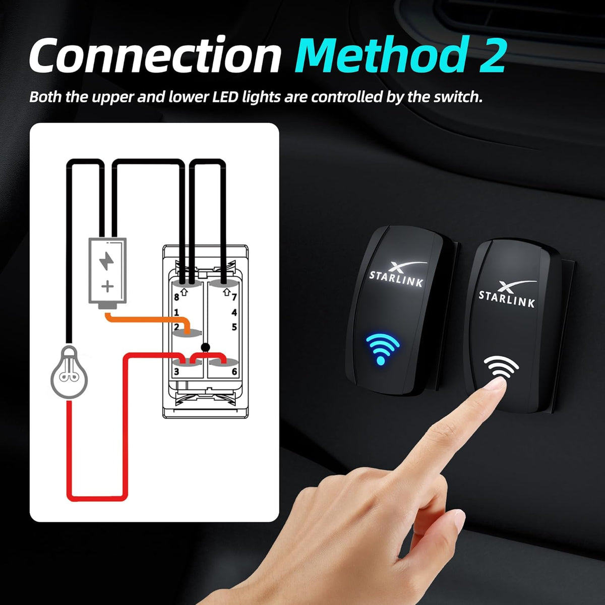
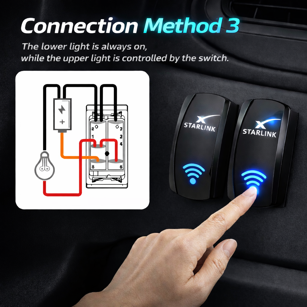
Two illuminated graphic areas can be wired in different ways to match your control-panel preference.
IP66 Housing
The switch body is listed for dust and water resistance in mobile and outdoor-oriented installations.
Compact Panel Fit
Rocker-style dimensions make it easier to integrate into an RV, truck, marine or off-grid control panel.
Match the Switch Rating to the DC Circuit Before Installation
The rocker switch controls the power circuit only. It does not convert voltage, regulate output or replace the correct Starlink power supply.
Designed to Integrate Into a Dedicated Power-Control Panel
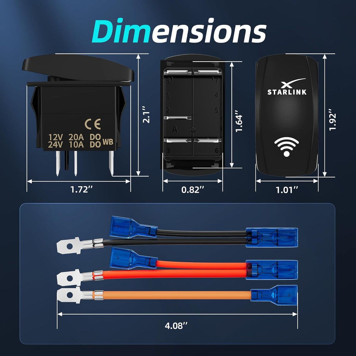
Current product dimensions show a front rocker face approximately 1.92 inches tall and 1.01 inches wide, with a compact rear terminal housing.
- Approx. 1.92 × 1.01 in front face
- Compact 5-pin rear terminal layout
- Supplied wiring leads shown in current package
- Measure the actual switch before cutting the final panel

Choose How the Switch Illumination Behaves
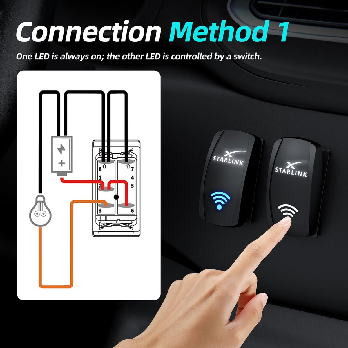
The upper graphic can be configured as a status light or controlled illumination depending on the selected wiring method.
The lower blue icon provides a second illuminated area for panel identification or switch-state indication.
Three wiring examples are shown in the current product instructions so the two LED areas can behave differently.
Its light state is determined by the electrical wiring of the rocker switch. It does not read Starlink connection status, signal strength or network quality.
Better Suited to RV, Marine and Off-Grid Panels Than an Open Indoor Switch
The current product is listed with an IP66 housing rating, making the front switch assembly more suitable for installations where dust, splashes or outdoor exposure can be part of daily use.
- IP66 product listing
- Dust-resistant switch housing
- Water-resistant rocker face
- Useful for protected RV and marine control panels

Configure the Indicator Lights Around Your Control-Panel Preference
The supplied wiring examples show three illumination behaviors. Follow the terminal diagram for the exact switch supplied with your order.

One illuminated area remains active while the other follows the rocker switch state.

Both illuminated areas turn on and off together with the switched circuit.

The lower icon stays illuminated while the upper indicator follows switch operation.
It Controls the Circuit — It Does Not Create the Correct Starlink Voltage
The rocker opens or closes a compatible low-voltage DC power circuit, letting you add convenient manual Starlink system control to a custom installation.
Voltage conversion, PoE injection and power regulation must still come from the correct external Starlink power supply, DC converter or compatible electrical system.
Put Starlink Power Beside the Other Systems You Already Control
Add Starlink to the same switch area used for lights, pumps and other travel electronics.
Create a clearly labeled power switch for a custom mobile-internet electrical installation.
Add manual Starlink circuit control to a suitable protected boat or cabin switch panel.
Shut the Starlink circuit down quickly when conserving battery power becomes important.
Use the Switch Where Your Starlink System Has a Compatible DC Control Circuit
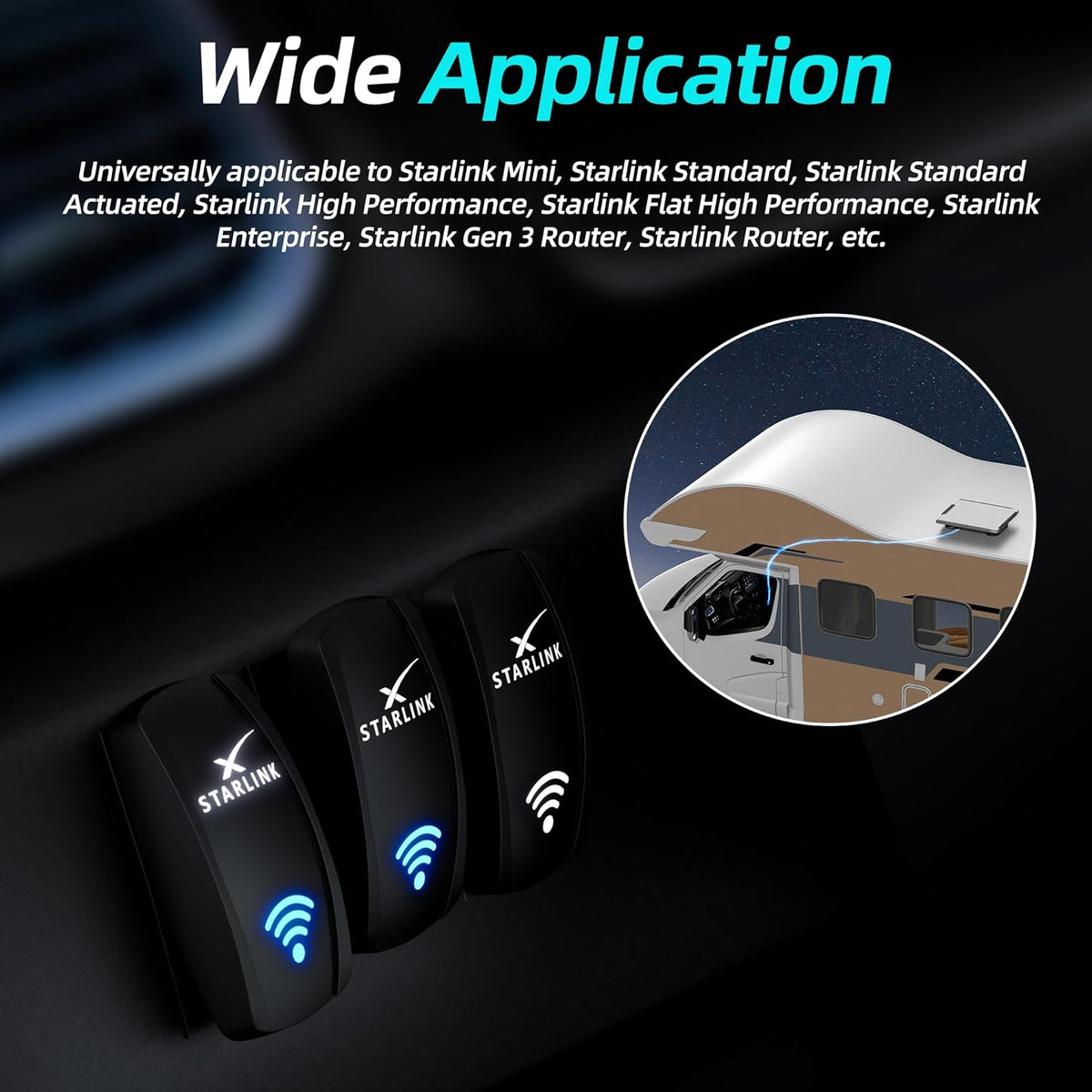
Current product media positions the switch for Starlink Mini and multiple Gen 1–3 installations. The important requirement is not the dish name alone — it is whether your converted DC power circuit matches the switch's electrical rating.
- Starlink Mini DC installations
- Compatible Gen 1–3 DC conversion setups
- Router or accessory control circuits where ratings match
- Custom RV / marine / vehicle power panels

“Fits Starlink” Does Not Mean It Replaces Every Starlink Power Supply
Starlink generations use different power architectures. Use this rocker only as part of a correctly designed DC circuit.
The rocker itself is labeled for 12V / 20A and 24V / 10A operation.
Confirm the expected continuous and startup current is appropriate for the switch and complete circuit.
Some Starlink systems require separate DC conversion, PoE equipment or specialized power adapters.
Gen 1, Gen 2, Gen 3 and Mini installations can have different voltage and network-power requirements. Install the rocker only in the appropriate compatible low-voltage control circuit.
Plan the Circuit Before Cutting the Panel
Disconnect power before installation. Confirm the wiring method, switch rating, fuse protection and mounting location before making permanent panel modifications.
Confirm the Circuit
Verify system voltage, current requirements and which side of the circuit will be switched.
Choose LED Behavior
Select the illumination method that best matches your control-panel use before connecting terminals.
Test Before Cutting
Bench-test switch function and lighting, and measure the actual supplied rocker body.
Mount & Recheck
Install the switch, protect the wiring and confirm normal Starlink operation under load.
Fuse the Circuit and Use Wiring Sized for the Actual Load
The rocker switch is one component in the power system. Safe performance depends on suitable wiring, terminals, circuit protection and the Starlink power architecture.
Install an appropriately sized fuse or circuit breaker for the connected wiring and Starlink power system.
Loose crimp terminals increase electrical resistance and can generate abnormal heat under load.
For high-current, high-inrush or professionally designed installations, a fused relay can allow the rocker to act as the control input rather than carrying the full load.
The Switch Rating Does Not Automatically Waterproof the Entire Panel
IP66 applies to the listed switch housing. Final installation weather resistance also depends on the panel cutout, rear terminals, wiring, seals and enclosure.
- Protect rear terminals from water exposure
- Use suitable sealed connectors where required
- Do not leave exposed terminals in wet areas
- Inspect outdoor wiring periodically for corrosion
Build the Starlink Power Circuit Around the System You Actually Use
Three complementary Tesstudio products for vehicle power, regulated Mini power and portable backup power.
Starlink Rocker Switch Questions
What does this Starlink rocker switch do?
It provides a dedicated manual ON / OFF control for a compatible low-voltage Starlink DC power circuit, reducing the need to repeatedly unplug the power connection.
What is the electrical rating?
The switch is labeled 12V / 20A and 24V / 10A. Your complete circuit, wiring, terminals, fuse and power equipment must also be correctly rated.
Is this a 5-pin switch?
Yes. The current product uses a 5-pin ON / OFF rocker design with dual LED illumination.
Is the rocker switch IP66 waterproof?
The switch housing is listed as IP66. Final installation weather resistance also depends on the panel, rear wiring, terminals, seals and enclosure.
Does the blue wireless icon show Starlink signal strength?
No. The illuminated icon is an electrical indicator built into the rocker switch. It does not communicate with Starlink and does not display Wi-Fi or satellite signal strength.
Can I choose how the two LEDs operate?
Yes. Current product diagrams show three wiring methods: one LED always illuminated with the other switch-controlled, both LEDs switch-controlled, or the lower LED always illuminated while the upper LED follows switch operation.
Is it compatible with Starlink Mini?
Yes, when used as part of a correctly designed compatible Starlink Mini DC power circuit that stays within the switch's voltage and current ratings.
Can it be used with Starlink Gen 1, Gen 2 or Gen 3?
The product is positioned for compatible Gen 1–3 DC conversion and control setups, but those Starlink generations use different power architectures. The rocker does not replace the required power supply, converter or PoE hardware.
Does the switch convert 12V or 24V to the voltage Starlink needs?
No. The rocker only opens and closes the electrical circuit. It does not increase, decrease or regulate voltage. Use the appropriate external converter or power supply required by your Starlink system.
Does it provide PoE power?
No. The switch is not a PoE injector, network adapter or router. Any required PoE equipment must be supplied separately by the compatible Starlink installation.
Can I install it in an RV or camper?
Yes. A rocker switch can be useful in RV, camper, truck and van control panels when the associated DC power circuit is correctly designed and protected.
Can I use it in a marine setup?
It can be used in an appropriate protected marine control-panel installation. Rear terminals, wiring, connectors and circuit protection must also be suitable for the environment and protected from corrosion.
What are the approximate dimensions?
Current product imagery shows a front rocker face approximately 1.92 inches tall by 1.01 inches wide. Measure the actual supplied switch before making a permanent panel cutout.
Are wiring leads included?
Current product imagery shows supplied short wiring leads with insulated terminal connectors. Refer to the package contents received with your switch before installation.
Do I need a fuse?
The power circuit should use correctly sized over-current protection appropriate for the wiring and connected equipment. The rocker switch itself does not replace a fuse or circuit breaker.
Should I use a relay?
A relay can be appropriate when the installation has higher continuous current, inrush current or when the rocker is intended only as a control signal. Follow the design requirements of your electrical system or use a qualified installer if unsure.
Why is my switch or terminal becoming hot?
Disconnect power immediately. Heat can indicate loose terminals, undersized wiring, excess current, corrosion or a poor crimp connection. Do not continue using the circuit until the cause has been corrected.
Is Starlink hardware included?
No. Starlink Mini, Starlink dishes, routers, vehicles, power converters and other equipment shown in product imagery are for demonstration only. This listing is for the rocker switch and supplied switch components.
Q&A
We provide assistance through email, live chat, and detailed installation guides. Additionally, we offer step-by-step tutorial videos featuring influencers to help you with the process.
We offer a one-year warranty (two years for some products).
Yes, the product can be removed after installation without affecting the original wiring harness of the vehicle.
We offer free returns and exchanges if there are any quality issues with the product upon receipt by the customer.

Subscribe
Join Us - Enjoy our latest news and exclusive discounts & gifts.